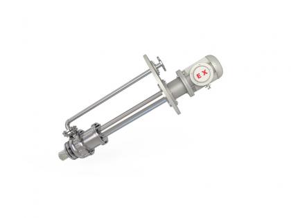
The G Type Sealed Single Screw Pump efficiently handles viscous fluids with sealed design, ensuring leak-proof operation and reliable performance in industrial applications.
MOQ:
1Package:
CustomziedColor:
CustomziedMaterial:
Stainless Steel/Cast Iron
Product Features
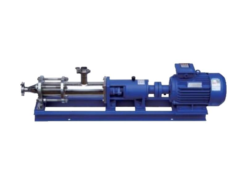
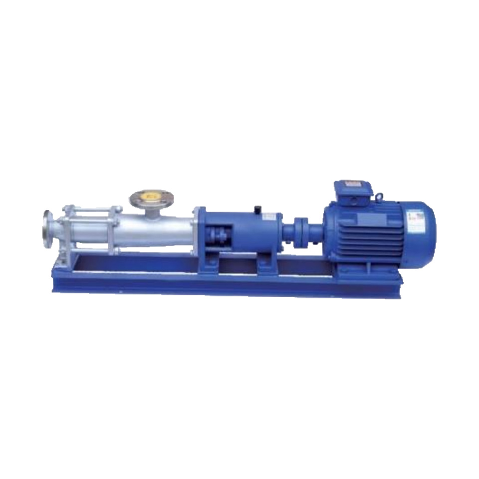
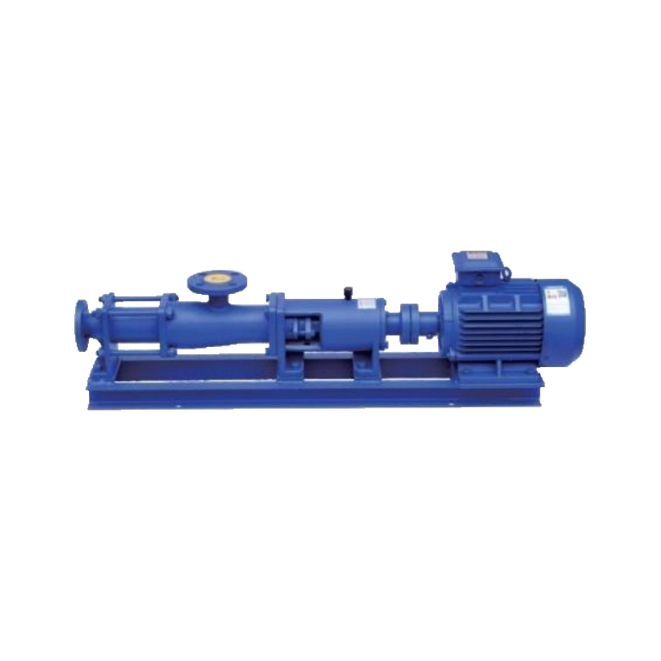
The G-type single-screw pump is an internally meshed, enclosed screw pump belonging to the category of rotary positive displacement pumps. Due to its strong adaptability to media, smooth flow, excellent suction performance, and minimal pressure pulsation, this pump can handle not only various flowable media but also highly viscous substances, media containing hard suspended or solid particles, and fibrous materials. It offers superior adjustability with a wide range, high efficiency, and is therefore widely applied across various industries such as environmental protection, marine, petroleum, pharmaceuticals, personal care, food, brewing, construction, mining, chemicals, printing, papermaking, power plants, and boilers.
Product Overview
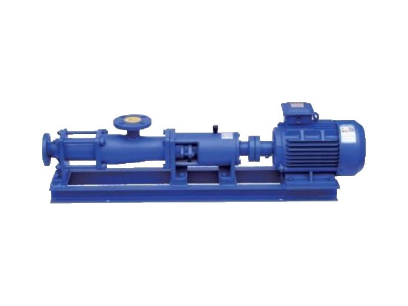
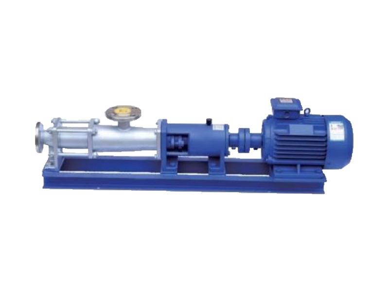
The G-type single-screw pump is a positive displacement pump featuring a helical rotor and stator, ideal for handling viscous, abrasive, or shear-sensitive fluids. It offers smooth flow, self-priming capability, and high efficiency in industries like wastewater, oil, and chemical processing. Its robust design ensures reliable performance with minimal maintenance.
Working Principle
The single screw pump is an internally meshing rotary positive displacement pump. Its main working components are an eccentric screw (rotor) and a fixed bushing (stator). Due to the unique geometric shapes of the rotor and stator, several separate sealed cavities are formed. As the rotor rotates, the medium within each sealed cavity is transported continuously, uniformly, and at a constant volume from the suction end to the discharge end.
Thanks to these characteristics, the single screw pump is particularly suitable for the following working conditions:
1.Handling highly viscous media
2.Transporting media containing solid particles or fibers
3.Applications requiring continuous, stable pressure without periodic fluctuations
4.Operations demanding minimal agitation to avoid damaging the inherent structure of the medium
5.Low-noise environments
Structural Diagram
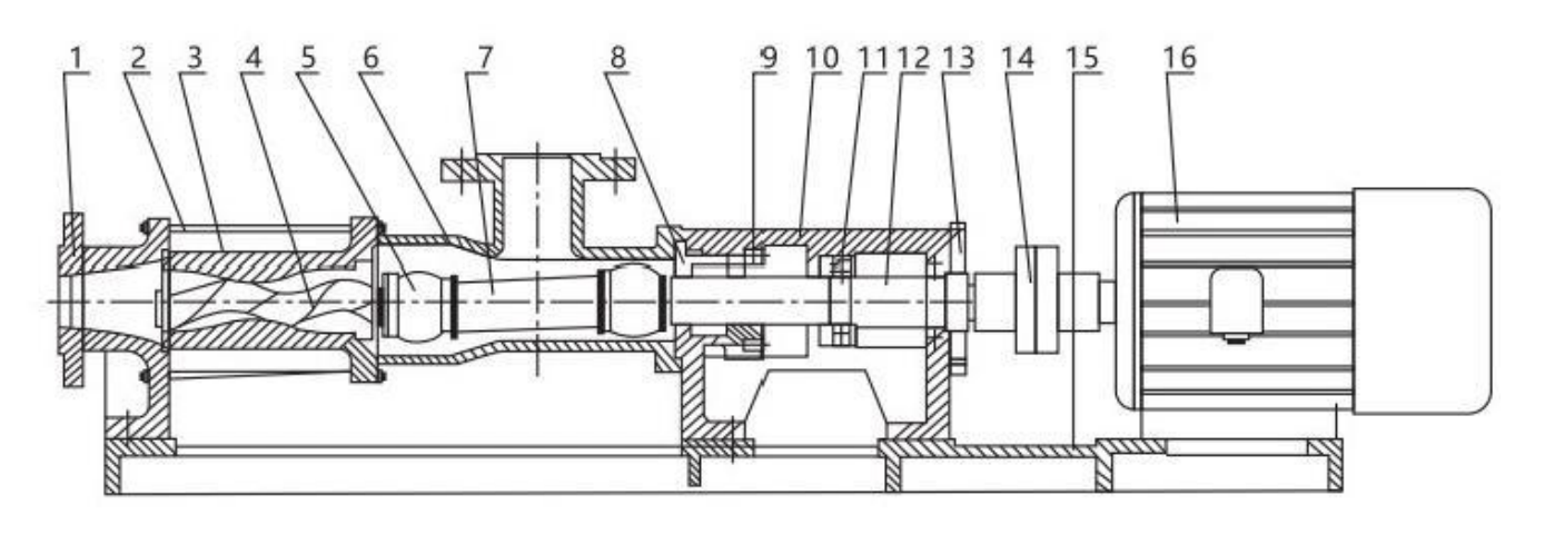
| No. | 1 | 2 | 3 | 4 | 5 | 6 | 7 | 8 | 9 | 10 | 11 | 12 | 13 | 14 |
| Name | Discharge Body | Tie Rod | Stator | Screw Shaft | Feed Body | Connecting Shaft | Packing Seat | Bearing Seat | Bearing | Drive Shaft | Bearing Cover | Coupling | Base Plate | Motor |
| Model | Flow Rate (m³/h) | Pressure (MPa) | Maximum Allowable Speed (r/min) | Motor Power (kW) | Required NPSH (m) | Inlet Flange Diameter (mm) | Outlet Flange Diameter (mm) | Maximum Allowable Particle Diameter (mm) | Maximum Allowable Fiber Length (mm) |
| G20 - 1 | 0.8 | 0.6 | 960 | 0.75 | 4 | 25 | 25 | 1.5 | 25 |
| G20 - 2 | 0.8 | 1.2 | 960 | 1.5 | 4 | 25 | 25 | 1.5 | 25 |
| G25 - 1 | 2 | 0.6 | 960 | 1.5 | 4 | 32 | 25 | 2 | 30 |
| G25 - 2 | 2 | 1.2 | 960 | 2.2 | 4 | 32 | 25 | 2 | 30 |
| G30 - 1 | 5 | 0.6 | 960 | 2.2 | 4 | 50 | 40 | 2.5 | 35 |
| G30 - 2 | 5 | 1.2 | 960 | 3 | 4 | 50 | 40 | 2.5 | 35 |
| G35 - 1 | 8 | 0.6 | 960 | 3 | 4 | 65 | 50 | 3 | 40 |
| G35 - 2 | 8 | 1.2 | 960 | 4 | 4 | 65 | 50 | 3 | 40 |
| G40 - 1 | 12 | 0.6 | 960 | 4 | 4 | 80 | 65 | 3.8 | 45 |
| G40 - 2 | 12 | 1.2 | 960 | 5.5 | 4 | 80 | 65 | 3.8 | 45 |
| G50 - 1 | 20 | 0.6 | 960 | 5.5 | 4.5 | 100 | 80 | 5 | 50 |
| G50 - 2 | 20 | 1.2 | 960 | 7.5 | 4.5 | 100 | 80 | 5 | 50 |
| G60 - 1 | 30 | 0.6 | 960 | 11 | 5 | 125 | 100 | 6 | 60 |
| G60 - 2 | 30 | 1.2 | 720 | 11 | 5 | 125 | 100 | 6 | 60 |
| G70 - 1 | 45 | 0.6 | 720 | 11 | 5 | 150 | 125 | 8 | 70 |
| G70 - 2 | 45 | 1.2 | 720 | 15 | 5 | 150 | 125 | 8 | 70 |
| G85 - 1 | 60 | 0.6 | 720 | 11 | 5 | 150 | 150 | 10 | 80 |
| G85 - 2 | 60 | 1.2 | 720 | 15 | 5 | 150 | 150 | 10 | 80 |
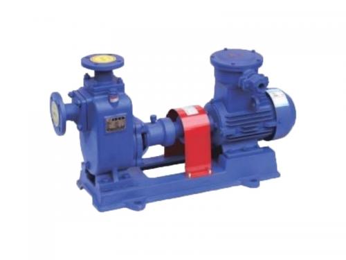
The CYZ - A self - priming oil pump is efficient. It features reliable self - priming, stable performance, and is suitable for various oil - transferring tasks.
Details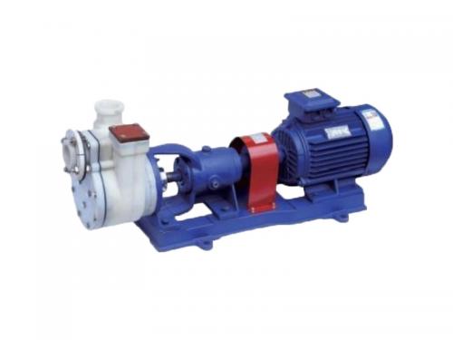
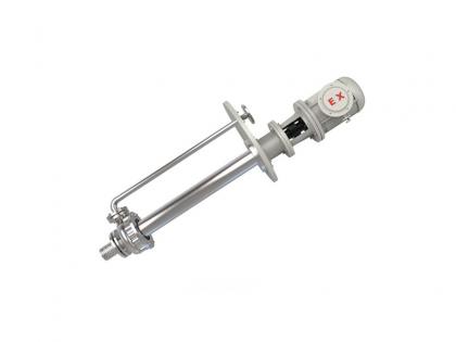
The FZB fluoroplastic alloy self-priming pump offers excellent corrosion resistance, high efficiency, and self-priming capabilities, ideal for harsh chemical environments.
Details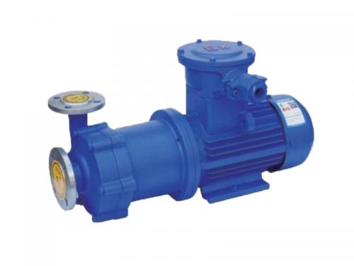
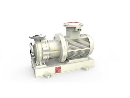
The CQ Magnetic Drive Pump features a seal-less magnetic coupling design, ideal for safe handling of hazardous, corrosive, or high-purity fluids. Energy-efficient, low-maintenance, and compact, it excels in chemical, pharmaceutical, and food processing applications.
Details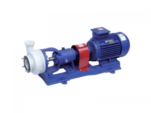
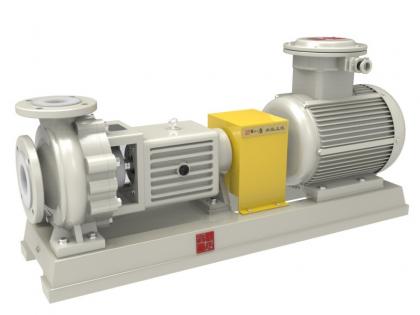
The FSB fluoroplastic alloy centrifugal pump offers superior corrosion resistance, high durability, and efficient performance for handling aggressive chemicals, acids, and solvents in demanding industrial applications.
Details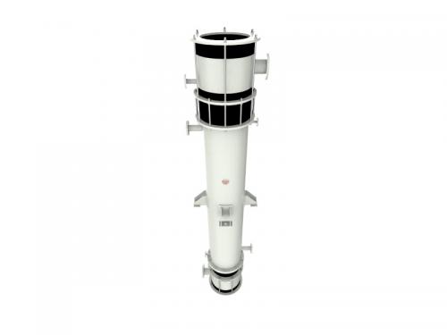
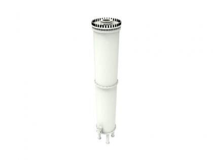
The Shell and Tube Graphite Falling Film Absorber efficiently absorbs gases using corrosion-resistant graphite, ensuring uniform liquid distribution and optimal heat transfer.
Details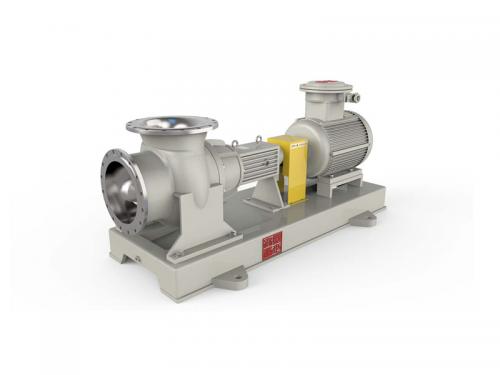
The axial-flow pump belongs to the category of pumps. It features an impeller that rotates around the axis. This impeller pushes water forward in the axial direction. As a result, the axial-flow pump is well-suited for applications involving large flow rates and low heads, such as irrigation and drainage systems.
Details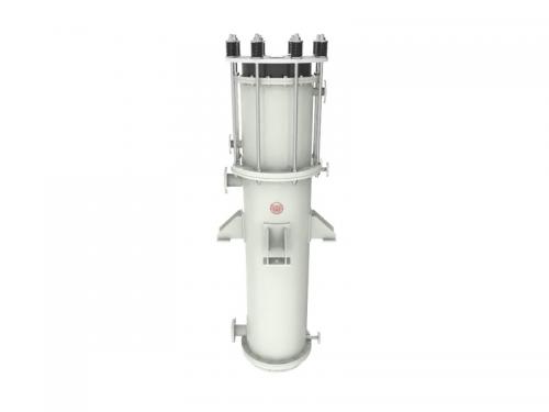
A Graphite Sulfuric Acid Dilution Cooler is a specialized device designed for the safe dilution of sulfuric acid and the subsequent cooling of the resultant mixture. This ensures that the chemical processing is carried out in an efficient and controlled manner.
Details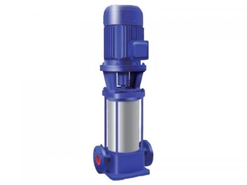
GDL vertical multistage pipeline pump ensures high-efficiency fluid transport, ideal for pressure boosting in industrial & water supply systems.
Details

Shengtang Road, Maolin Town, Jingxian City, Anhui Province, China (factory)

Acid and alkali resistant chemical pump and intelligent filtration system integrated supplier


 IPv6 network supported
 English
 français
 русский
 español
 português
 العربية
 ไทย
ไทย Tiếng Việt
 Indonesia
  中文
中文