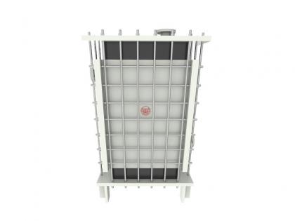
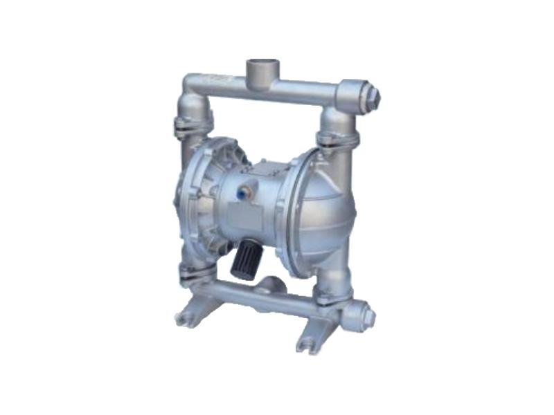

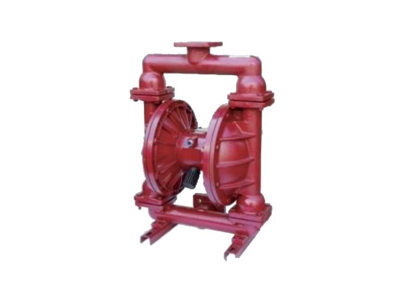
QBK Leak-Free Pneumatic Diaphragm Pump: Compact, corrosion-resistant, energy-efficient, ideal for chemical transfer. Zero leakage, low maintenance, durable for harsh environments.
MOQ:
1Package:
CustomziedColor:
CustomziedMaterial:
Cast iron/Stainless steel/Fluorine-linedWorking Temp:
Working Pressure:
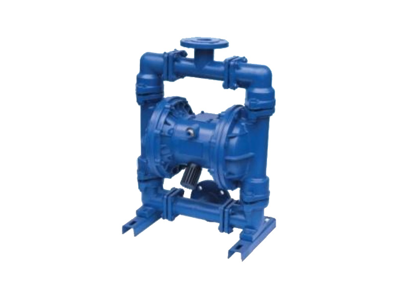
Product Overview
The QBK pneumatic diaphragm pump can transport both free-flowing and viscous fluids, offering the combined benefits of self-priming, submersible, canned motor, slurry, and trash pumps with no need for priming (7m suction lift, 70m head, ≥6kgf/cm² outlet pressure), a wide flow path for 10mm solids with minimal wear, adjustable flow/head via air valve (1-7kgf/cm²), leak-free operation for hazardous chemicals, explosion-proof air operation, submersible capability, automatic dry-run/overload protection, low maintenance with no media contact to moving parts, 10,000 cP viscosity handling, and lubrication-free durability even during dry running, making it ideal for tough industrial applications.

Main Applications
The QBK pneumatic diaphragm pump is widely used for handling food products (peanut butter, pickles, mashed potatoes, sausages, chocolate, hops, syrup), paints and adhesives, ceramic glazes, abrasives and corrosive agents, toxic/flammable liquids, wastewater and cement grout, strong acids/alkalis, and as a pre-pressure feeding device for solid-liquid separation systems.
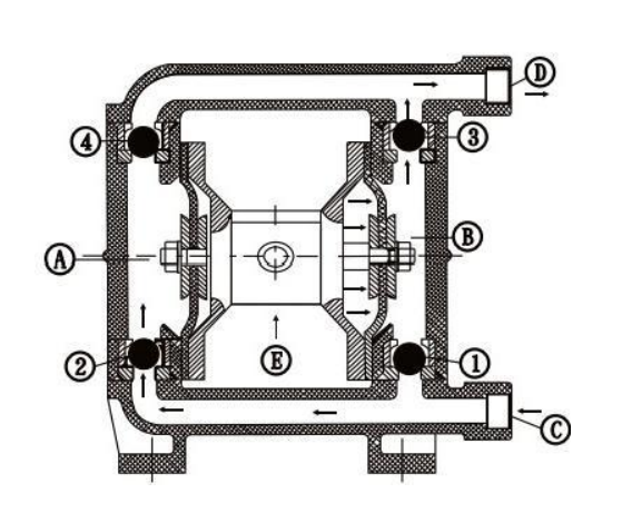
Working Principle
The QBK pneumatic diaphragm pump features two symmetrical working chambers (A and B), each equipped with a diaphragm connected by a central linkage. Compressed air enters through the intake port and is directed by an air distribution valve into one chamber, forcing its diaphragm to move while expelling air from the opposite chamber. At the end of each stroke, the valve automatically switches airflow to the other chamber, reversing diaphragm movement and creating continuous, synchronized reciprocation.
In operation:
1.Air enters the distribution valve (port ⑤), pushing the right diaphragm outward.
2.Chamber A generates suction, drawing media through inlet ③—opening ball valve ② to fill chamber ④ while valve ④ closes.
3.Simultaneously, chamber B compresses media, forcing it through outlet ① via ball valve ③ (ball valve ① closes to prevent backflow).
4.This cycle repeats, enabling continuous suction at inlet ③ and discharge at outlet ①.
Others
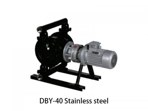
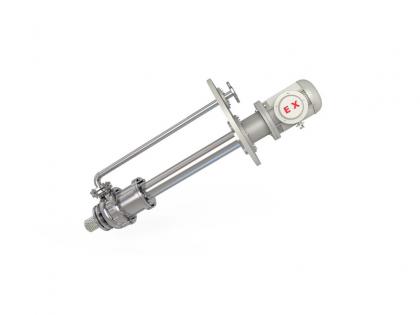
The DBY New Type Electric Diaphragm Pump offers efficient, leak-free fluid transfer with durable construction, low energy consumption, and quiet operation for industrial applications.
Details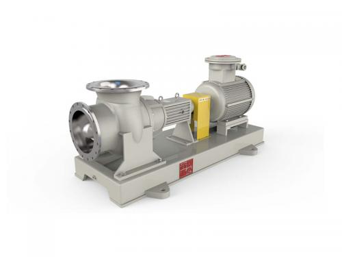
The axial-flow pump belongs to the category of pumps. It features an impeller that rotates around the axis. This impeller pushes water forward in the axial direction. As a result, the axial-flow pump is well-suited for applications involving large flow rates and low heads, such as irrigation and drainage systems.
Details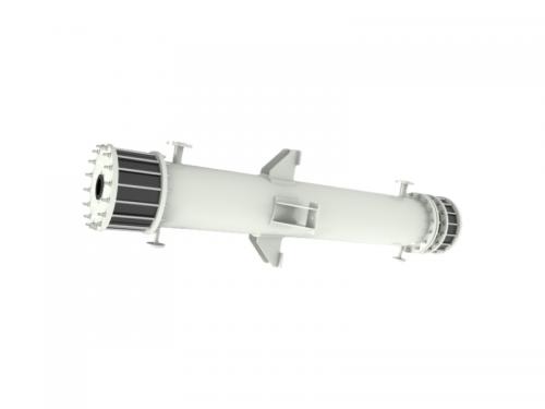
The tubular graphite heat exchanger is a type of heat transfer equipment fabricated from graphite. It exhibits excellent corrosion resistance and is extensively utilized in industries such as chemical and petrochemical for highly efficient heat exchange processes.
Details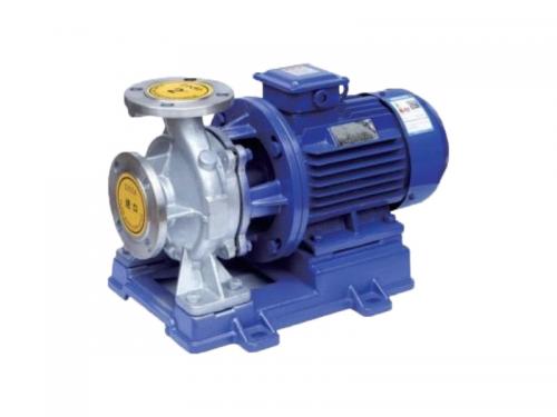
The ISW horizontal centrifugal pump is a single-stage, single-suction design for efficient fluid transfer in pipelines, HVAC, and water supply systems.
Details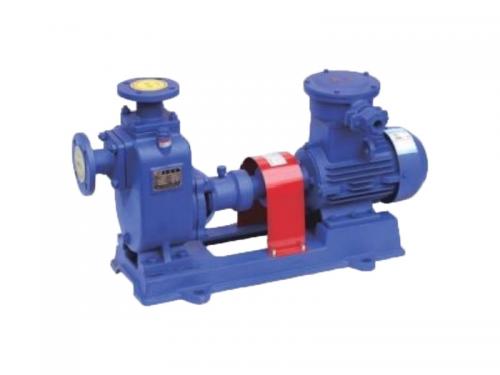
The CYZ - A self - priming oil pump is efficient. It features reliable self - priming, stable performance, and is suitable for various oil - transferring tasks.
Details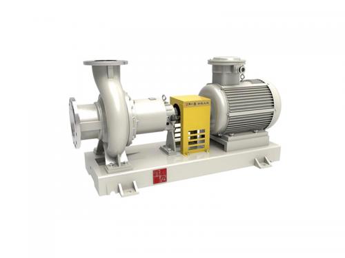
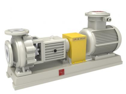
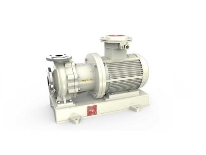
The TCA/E no-leakage petrochemical magnetic pump is specifically engineered for application in the petrochemical industry. Its most notable feature is the absence of leakage, which significantly enhances operational safety. By virtue of being constructed with high-quality materials and incorporating advanced technological elements, this pump offers a high degree of reliability. In addition to its functional advantages, the pump has a compact design. This characteristic makes it not only easy to install but also convenient for maintenance. As a result, it can efficiently facilitate the transfer of fluids even within the demanding and harsh conditions prevalent in the petrochemical environment.
Details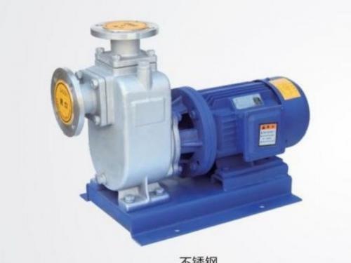
The Industrial Self Priming Centrifugal Pump efficiently transfers various liquids without manual priming. Ideal for industrial applications, it offers high performance, reliability, and easy maintenance, ensuring continuous and smooth operation.
Details
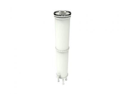
Shell and tube graphite falling film absorbers are specialized devices used in various industrial applications for their excellent thermal and chemical resistance properties. These absorbers are designed to efficiently absorb gases while providing effective cooling and separation processes.
Details

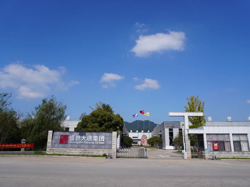
Shengtang Road, Maolin Town, Jingxian City, Anhui Province, China (factory)

Acid and alkali resistant chemical pump and intelligent filtration system integrated supplier


 IPv6 network supported
 English
 français
 русский
 español
 português
 العربية
 ไทย
ไทย Tiếng Việt
 Indonesia
  中文
中文